




تحت الأرض أنابيب شاملة معرض مكونات عملية التصنيع الجاهزة مفصلة
أولا ، إعدادات المكان
موقع جاهز
1. يتم اختيار الموقع وفقا للحالة الفعلية للمشروع. يعتمد الموقع إدارة مغلقة لإنشاء عمليات الاستيراد والتصدير ، ويتم حجز طريق الوصول إلى البناء في منطقة تخطيط الموقع ، ويتم تعليق العلامات المختلفة عند الاستيراد والتصدير وفقًا للوائح.
2. يجب أن يكون تخطيط موقع التجهيز المسبق متوافقاً تماماً مع متطلبات المعيار القياسي ، وأن يفي بمتطلبات نظام إدارة الصحة والسلامة المهنية وإدارة البيئة ، وتعليمات تشغيل HSE ، وأن ينشئ العديد من مرافق حماية بيئة السلامة. يجب أن تكون مجهزة بالكامل لتلبية متطلبات الإنتاج الآمن والحضاري وتصريف مياه المجاري والتخلص من القمامة. بدقة وفقا للأحكام ذات الصلة من الإدارات الحكومية المحلية.
3. تنظيف الموقع الجاهز ، التسوية ، الإهتزاز والضغط ، وضع قاعدة أسمنتية مكونة من 20 سم استقرت على قاعدة المكادم ، تمليس وتهتز وضغط. سوف الطريق الرئيسي للمصنع صب الخرسانة التجارية C20 15CM سميكة على قاعدة المكاديم الاسمنت استقرت. ، منطقة التثبيت ، الجاهزة ، منطقة الإنتاج ، معرض الأنابيب المتكاملة منطقة الحفاظ على البيئة الطبيعية صب 10cmC20 التجارية ملموسة. في موقع تركيب الرافعة الجسرية ، يبلغ عمق الحفر 60 سم ، ويتم سكب الخرسانة ووضع المسار. أيضا القيام بهذه الأشياء الثلاثة:
(1) يجب تنظيف الموقع وتسويته ، بما في ذلك المواقع الجاهزة ، وربط أحزمة عمل البناء وطرق النقل الموجودة ، والممرات في المواقع الجاهزة.
(2) في الموقع الجاهز ، يجب تنظيف الحجارة ، والأعشاب الضارة ، والأشجار ، والبنى ، وما إلى ذلك التي تؤثر على مرور أو أعمال البناء لآلات البناء ، ويجب تسوية الخندق والجبال ، والمناطق المنخفضة مع المياه المتراكمة ينبغي تصريفها وشغلها ، إذا لزم الأمر ، تغيرت. ملء ، ضمان كامل التسطيح للأرض والقدرة على التحمل والضغط.
(3) يجب أن يتم تنظيف الموقع قبل التسوية من أجل الحفاظ على الأرض أو احتلال الأرض ، وعدم وجود عرقلة في حركة المرور ، وعدم إلحاق أضرار بالمباني والمرافق والآثار وغيرها ، لمنع التلوث البيئي وتآكل التربة.
4. التصنيع المسبق لمنطقة تجهيز وتجهيز قضيب فولاذي ، منطقة تبخير معرض تصنيع الأنابيب الجاهزة ، معرض متكامل للأنابيب ، مستودع تخزين الأنبوب المتكامل ومناطق وظيفية أخرى. يتم تعيين منطقة المكتب ومنطقة المعيشة وفقًا للحالة الفعلية ، ويتم إعداد مدخل ومخرج المجال الجاهز كغرفة للحراسة. الثانية ، عملية الإنتاج
مخطط تدفق عملية الإنتاج
1. تعزيز مواد البناء الهندسية دخول الموقع ، والتفتيش أخذ العينات ، وتجهيز الصلب ، وربط شريط الصلب ، والتركيب.
(1) التفتيش نهج التعزيز أ. حديد التسليح هو الفولاذ المدرفل على الساخن من فئة HPB300 والصلب المدرفل على الساخن HRB400. تفي القوة القياسية لشريط الفولاذ بمتطلبات 4.2.2 من GB50010-2010. يتوافق قضيب الفولاذ المضلع مع الفولاذ للخرسانة المسلحة: الجزء الثاني: قضبان فولاذية مضلعة مدرفلة على الساخن (GB1499.2-2007) ؛ القضبان الفولاذية ذات الدوران الخفيف تلبي متطلبات الصلب للخرسانة المسلحة: الجزء الأول: قضبان الصلب المدلفنة على الساخن (GB1499.1-2008). صفيحة فولاذية مصنوعة من فولاذ Q235-B ، ملحوم إلكترود لحام فولاذ HPB300 مع إلكترود نوع E43 ، ولحام الفولاذ HRB400 ملحوم بقطب نوع E55. ب. قبل دخول الصلب إلى الموقع ، تحقق من قائمة الأصناف ، والمواصفات ، والمواصفات ، والكمية ، والمواد ، بما يتفق بدقة مع المتطلبات ، سواء كانت شهادة جودة المنتج ، وتقرير فحص المصنع ، وتقرير إعادة التفتيش مكتملة وصالحة. يجب أن يكون اختبار الخصائص الميكانيكية وفقا للمعايير ذات الصلة. ج. قبل دخول الصلب إلى الحقل وقبل الاستخدام ، تحقق من جودة مظهر شريط الفولاذ ، سواء كان مستقيمًا أو ضررًا أو إدراج خبث على السطح أو الجلد الثقيل أو الكراك أو بقع الزيت أو الصدأ القديم أو الحبيبي أو اللون الموحد ، عرض قطر شريط الصلب تلبية المتطلبات ، حتى لا تؤثر على قوة الصلب وأداء رسو. يتم فحص ألواح الصلب ، قضبان اللحام ، الخ بمواد فحص قضيب فولاذي قبل دخول الموقع.
(2) تخزين قضبان الصلب يتم تخزين الأشرطة الفولاذية التي تدخل الموقع في منطقة تخزين قضيب من الصلب وفقًا للتنوع والمواصفات والصف. يتم تخزين المواد من قبل موظفي المواد والحراس. مطلوب شريط الصلب لتغطيتها مع وسادة لمنع الصدأ. ب. تحقق مما إذا كان شريط الفولاذ لديه شهادة المصنع وتقرير فحص المصنع وتقرير إعادة التفتيش. تحقق من جودة المظهر وقطر ممثل الحجم. يجب فحص شريط الفولاذ بشكل شامل لمؤشر الجودة الخاص به. وفقاً لفحص الدفعة ، يكون قطر وانحراف الوزن هو نفس المصنع ، نفس رقم الفرن ، نفس المواصفات ، نفس عملية الإنتاج ، و شريط الصلب 60 طن الذي يدخل نفس موقع البناء في نفس الوقت نصيب استقصاء ، أقل من 60 طنًا. أيضًا كاختبار ، قم بإجراء أخذ العينات. يتم إجراء أخذ العينات من قضبان الصلب من قبل المهندس المشرف. يجب أخذ قضيبين من الصلب لأخذ قطعتي اختبار الشد ، كل منهما بطول حوالي 450 ملم ، واثنان من قطع الاختبار البارد مع طول حوالي 350 ملم ، وضعت في مربع الاختبار ، ثم أشرفت على الختم أو المراقبة غرفة الاختبار. إذا كانت نتيجة تقرير إعادة الفحص غير مؤهلة ، يجب أن تكون عينات مزدوجة وإعادة اختبارها. تكون نتائج تقرير إعادة الفحص مؤهلة ، ويوقع مهندس الإشراف المهني على الموافقة ، ويمكن استخدام مجموعة قضبان الفولاذ في المعالجة. يتم تخزين وتخزين المواد الأخرى عن طريق عزل الرطوبة.
(3) معالجة حديد التسليح قبل المعالجة ، وفقا لمواصفات التصميم والطول والكمية ، جنبا إلى جنب مع تقنيات المعالجة المختلفة ، يتم تحديد طول كل حديد التسليح من خلال الحساب لضمان الدقة. أثناء المعالجة ، تحقق مما إذا كان هناك أي خطأ أو إهمال في جدول الطمس. تحقق من جدول المواد لكل نوع من أنواع قضيب الفولاذ. بعد هذين الفحصين ، اضغط على جدول المواد لتحرير العينة الحقيقية. بعد تأهيل الإنتاج التجريبي ، يمكن معالجته على دفعات. يجب تكديس القضبان الفولاذية الجيدة بشكل منظم ومنظم. يجب أن يكون سطح قضيب الفولاذ نظيفًا ، ويجب تنظيف الشحوم والأوساخ والصدأ قبل الاستخدام. يتم تقويم القضبان الفولاذية وتصفيتها ميكانيكياً. لا يجب أن يكون للقضبان الفولاذية بعد تقويمها الانحناء المحلي أو الانحناءات الميتة أو الأمواج الصغيرة. يجب أن يكون قطع شريط الفولاذ على أساس شريط الفولاذ ، القطر ، الطول والكمية. يجب كسر طول وطول القضيب الفولاذي ويجب كسر المادة القصيرة أولاً ، ويجب تقليل رأس الصلب القصير وتقصير قدر الإمكان لتوفير الفولاذ وتقليل الخسائر. عندما ينحني قضيب الفولاذ ، فإن الحصة تحدد نقطة الانحناء وتحدد زاوية الانحناء على أساس قوة الارتداد لكل قضيب فولاذي. قبل الانحناء الرسمي ، ستخضع القضبان الفولاذية التي تم ثنيها بكميات كبيرة للانحناء التجريبي وسيتم تحديد البيانات الفنية ذات الصلة قبل ثني الدُفعات. بعد أن ينحني قضيب الفولاذ ، يشكل القوس قوسًا. بعد الانحناء ، لا يكون الحجم أكبر من حجم المسح. ينبغي النظر في قيمة تعديل الانحناء. لا يقل قطر الثني D للشريط الفولاذي المنحني والانحناء في الجزء الأوسط عن قطر قضيب الفولاذ بمقدار 5 أضعاف. يجب اعتبار طول قضيب الفولاذ بشكل شامل وفقًا لحجم المكون ، وسماكة الطبقة الواقية ، وقيمة الضبط لثني القضيب الفولاذي. يجب ألا يتجاوز الانحراف المسموح به لتجهيز قضيب الفولاذ المواصفات. بالنسبة للقضبان الفولاذية ذات المواد النهائية غير الكافية ، يتم استخدام طريقة اللحام بالضغط بعقب المفصل لتثبيت طول القدم ثم الانحناء. يجب تدريب عامل اللحام على عملية لحام خاصة ومعاينة للتفتيش. بعد تشكيل القضبان الفولاذية المختلفة ، يجب ألا يتجاوز الانحراف المسموح به المواصفات: يجب أن يكون طول أضلاع القوة الكاملة ± 10 مم ؛ يجب أن يكون انحراف طول كل جزء من الركائب ± 5 مم ؛ يجب أن يكون انحراف الأضلاع المنحنية ± 20 مم من العضو ، حجم كبير تكون الخرسانة ± 30 مم ؛ الانحراف من زاوية الصلب هو 3mm. الضلع المستدير 6 ~ 12mm مصنوع في الرِّكاب ، وطول خطاف الوصلة هو 75 ~ 105mm طبقاً لقطر الضلع الرئيسي. يتم تحديد الحساب المحدد قبل الطمس ، يتم تصنيف القضبان الفولاذية المعالجة وتخزينها ، ويتم منع قضبان الصلب المشكلة من التشوه أثناء التخزين والنقل.
هيكل مضفر (حديد مقوى) صندقة فولاذية
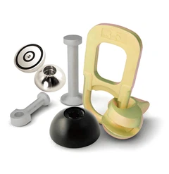
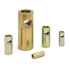
الصعوبات: الصعوبة في صنع الأضلاع الرئيسية للأنبوب العلوي المستطيل هي الضلع الرئيسي للضلع الخارجي. كل حلقة تتكون من أربعة قضبان فولاذية ذات قوسيْن ، كل منها عبارة عن حلقة حديدية مستطيلة العلوية مستطيلة الشكل. نصف قطر القوس صغير جدًا ، وقوس القوس المنحني قصير ، والدقة عالية. . الحل: قبل أن تنحنى القضبان الفولاذية ، ضع عليها علامة عند تقاطع كل قوس. بعد ذلك ، ينحني قوس درجة R90 بواسطة ثني ثلاثي القوائم ، ولا ينحني الجزء المستقيم. بعد انحناء القوس بالكامل ، يتم وضعه على الفحص الرئيسي القياسي. بعد استيفاء المتطلبات ، يتم وضع علامة موقف حركة عجلة الحركة المتحركة على منصة تشغيل آلة الثني للإنتاج السريع التالي. تحتاج آلة الثني الثلاثية إلى وظيفة الركض والعكس. (4) لحام الصلب شريط وضعت شريط الصلب شكلت على أداة لحام شريط الصلب وفقا لرسومات البناء لحام. تعتبر جودة اللحام جزءًا مهمًا لضمان القوة الكلية لشريط الفولاذ. في مصنع معالجة قضيب فولاذي ، يتم تنظيف قضبان الفولاذ بشكل رئيسي عن طريق اللحام بعقب الفلاش المزدوج الجوانب لتنظيف نتوءات الزاوية وصدأ وجه النهاية ، بقع الزيت وأكسيد الطبقة قبل أن يتم لحامها ، ويتم كشف اللمعان المعدني بواسطة الطحن ، و لا توجد ظاهرة أكسدة. في الوقت نفسه ، يجب تسوية الوجه النهائي لشريط الصلب لتسهيل تركيبة جيدة. يجب أن تتم محاذاة التركيبات على كلا الجانبين للتأكد من أن القضبان الفولاذية على نفس المحور ، وأن التفريغ المحلي للقضبان الفولاذية لا يزيد عن 3 مم. يجب أن يكون الضغط المطبق أثناء اللحام متجانسًا وقويًا ، ويجب التحكم بدرجة الحرارة عند 30-40 ميجا باسكال بناءً على قطر قضيب الفولاذ لتحقيق الالتصاق الجيد بين قضيبي الصلب. عندما تكون القضبان الفولاذية ذات الأقطار المختلفة ملحومة ، يجب ألا يتجاوز الانحراف 7 مم. إن لحام اللحام واللحام البارد يتماشى مع اللوائح بشكل صارم ، ويتم اعتماد عمال اللحام للعمل. بعد الانتهاء من اللحام ، سيتم تغيير المفصل من الأبيض إلى الأسود لتحرير المشبك ، وسيتم سحب شريط الفولاذ بسلاسة لتجنب الانحناء. بعد الانتهاء من لحام القضبان الفولاذية ، يجب إجراء فحص مظهر المفاصل الملحومة في الوقت المناسب ، كما يجب إعادة لحام المفاصل التي تفشل في الفحص البصري. يجب على جميع مشغلي اللحام التأكد من أن جميع أنواع آلات اللحام في حالة عمل جيدة ، وإتقان الأداء الرئيسي ومعلمات آلات اللحام المختلفة في الوقت المناسب ، واختيار أفضل المعلمات للتشغيل الفعلي وفقًا لظروف المعدن الأساسي والطقس لضمان جودة اللحام. . (5) يجب إعادة معايرة الأقفاص الفولاذية المقواة قبل المواصفات والحجم والشكل والكمية والأدوات لتحديد المواقع ، وما إلى ذلك ، ويجب إجراء الفحص الشامل وفقاً لرسومات التصميم وقائمة المكونات. يمكن مطابقة التصميم وقائمة المكونات والأشياء المادية. الأمان. قبل تثبيت النظام ، يتم ترتيب التعزيز على منصة الأدوات لتحديد المواقع وفقًا لبيانات التصميم. في الوقت نفسه ، وفقا للموقع ، يتم تحديد وضع التعزيز المستمر لضمان أن قضبان الصلب بعد التثبيت تفي بالمتطلبات. في عملية الأمان ، يتم تصنيع قضبان الفولاذ بشكل أساسي عن طريق سلك الربط واللحام. مصنوعة من الثقوب 20 ~ 22 # سلك. طريقة الربط والربط مطابقة للمواصفات واللوائح. يستخدم لحام البقعة بشكل رئيسي في تشكيل قضبان الصلب والقضبان الثابتة. التثبيت ، يجب أن يكون لحام البقع ثابتًا ، يجب توزيع النقاط بالتساوي ، ويجب ألا تتضرر أضلاع القوة بشكل خطير. يجب أن يفي مفصل الجلد من القضيب الصلب بالمتطلبات التالية: أ. يجب ألا تقل نهاية طول اللفة عن 10 أضعاف قطر القضيب الصلب عند منحنى القضيب الفولاذي ، ولا يجب وضع المفصل في أقصى لحظة انحناء للمكون. ب. في منطقة التوتر ، يجب أن تكون نهاية وصلة ربط الصلب من الدرجة I في خطاف. في نفس القسم ، يجب أن تكون مساحة المقطع العرضي لمفصل منطقة التوتر أقل من 50٪ من المساحة الكلية لمفصل المتلقي ، ولا يجب أن يكون مفصل الجلد أكثر من 50٪. لا يزيد عن 25٪ ، في نفس الوقت ، يجب ألا تتجاوز مفاصل الجلد 50٪ في منطقة الانضغاط. ج. مفاصل معززة ، مربوطة بالأسلاك في المركز وعند كلا الطرفين. د. المواقف المشتركة للضلوع المجهدة متداخلة من بعضها البعض. يجب أن يفي طول اللفة للمفاصل المقواة بالفولاذ المشدد بمتطلبات التصميم الإنشائي. يجب وضع المفاصل الفولاذية الملحومة والمفاصل الميكانيكية في الحد الأدنى من لحظة الثني والتراكم. ه. عندما يكون قطر قضيب الفولاذ المجهد ≥25mm ، لا ينصح باستخدام وصلة ربط غير ملحومة. F. يجب أن تفي سماكة طبقة الحماية الخرسانية لشريط الصلب المجهد بمتطلبات التصميم الإنشائي. من أجل ضمان الوضع الصحيح لشريط الفولاذ ، يتم ربطه وتثبيته وفقًا لمتطلبات التصميم. ز. في عملية ربط القفص التسليح ، يتم توجيه أنبوب ΦPVC واحد مدفون مسبقًا على الجوانب الأربعة للمفصل ، Φ14mm ، يتم تحديد طول أنبوب PVC وفقًا لسمك جدار فم المفصل ، و PVC المضمن مسبقًا يتم استخدام الأنابيب كفتحة للتفتيش وثقب الحقن. يتم تركيب فتحات الرفع على 500 مم فوق وتحت المحور المركزي للجانبين الأيسر والأيمن من معرض الأنبوب المتكامل. يتم لحام أنبوبين فولاذيين Φ125 * 10mm * 220mm بالإطار الفولاذي ، ويتم استخدام لوحة فولاذية Φ140 * 4 للإحكام. يتم تركيب الأنابيب الفولاذية Φ125 * 10mm * 180mm قبل رفعها. يستخدم دبوس الحديد Φ110mm * 350mm كأذن شماعات الأنبوب المتكاملة لتلبية بناء الرفع في معرض الأنبوب المتكامل. أعمال الصلب المقوى هي مشاريع مخفية. قبل صب الخرسانة ، يجب فحص قضبان الصلب والأجزاء المدمجة وقبولها ، ويجب أن يتم عمل السجلات الهندسية المخفية. بعد موافقة مهندسي الإشراف في الموقع ، يمكن تنفيذ العملية التالية.
التجمع العفن الصلب
يجب أن تكون الطريقة الأكثر كفاءة لعملية التجميع هي: أولاً دعم القالب الداخلي ، يجب أن يتم لحام أضلاع ربط طوق الفولاذ أولاً ثم توضع في القالب السفلي ، ويجب لحام الحلقة المبطنة من الصلب التي تربط أضلاع المقابس بعد الفولاذ يتم وضع الإطار في القالب ، ويتم لحام قضبان الصلب. بعد وضع الهيكل العظمي في القالب ، يتم لحام كل من ثقب الحشو ، ثقب التجصيص والصفائح الفولاذية المسبقة. بعد اللحام ، يتم تجميع القالب الخارجي. من أجل منع وضع ثقب الرفع من عدم الدقة ، يتم تثبيت فتحة الرفع على القالب الخارجي ، ويتم تجميع القالب الخارجي ومن ثم يتم إعداد مقبس اللحام مسبقًا. حلقة الصلب المدفونة. (6) الطبقة الواقية المقواة الطبقة الواقية للخرسانة مصنوعة من كتلة خرسانية ، سماكة تساوي سماكة الطبقة الواقية المصممة ، حجم الكتلة 3 سم × 3 سم ، رقم الوسادة هو أكثر من قوة الهاون C25 ، و يتم تعزيز علاج أثناء الإنتاج لتحقيق قوة التصميم. 85 ٪ من ما سبق يمكن استخدامها. عند استخدامها في الهيكل الرأسي ، يمكن أن يتم دفن خط ربط # 20 في الكتلة ، وترتبط الكتلة بشريط الفولاذ بالسلك. يتم وضع الطبقة السفلية من اللوحة السفلية وطبقة تعزيز الجدار بمقدار متر مربع واحد لكل متر مربع ، ويتم ترتيب أزهار البرقوق. يجب أن تكون المسافات بين الوسائد مشفرة بشكل صحيح. بشكل معقول ترتيب الكتل ، وربطها بإحكام على قضبان الصلب المجهدة ، بدلا من وضعها على الأوتار غير المجهدة ، يجب أن يكون التثبيت ثابت لمنع النزوح والانزلاق أثناء عملية الصب ؛ ما إذا كانت الكتل يتم تفتيشها بالكامل قبل صب الخرسانة مفقودة أو تالفة. 2. صب الخرسانة (1) المواد الخرسانية يتم نقل النقل الخرساني إلى الموقع الجاهز بواسطة صهريج خرساني ، ويتم ضخه في المستودع بواسطة شاحنة ضخ الخرسانة. يتم التحكم في هبوط الخرسانة بشكل عام بين 140 و 180 ملم (تعتمد القيمة المحددة على درجة حرارة اليوم). 4 قضبان هزازة ملموسة مع دائرة نصف قطرها 20-25 سم ، لذلك التباعد بين كل قضيب هو 40 سم. كل عمق قضيب هو في حدود 5cm تحت سطح اهتزاز السابقة ، والوقت تهتز في كل قضيب 2-3 دقائق. (2) تصميم خلط نسبة واختبار أ. تصميم نسبة الخلط لتلبية متطلبات قوة التصميم الخرسانية ، مقاومة الصقيع ، النفاذية ، معدل تمدد الرمل الكلي وقابلية التشغيل ، اختبار تحسين نسبة خلط الخرسانة في نفس الوقت ، يفي بمتطلبات نسبة البناء والاسمنت في المياه والركود ، ويتم مراجعتها والموافقة عليها من قبل مهندس الإشراف. يجب أن تضمن نسبة خلط الخرسانة أن الخرسانة التي تم الحصول عليها يمكن أن تلبي ظروف الصب المحددة ، واستهلاك المياه في نسبة خليط الخرسانة صغير قدر الإمكان. ب. خطة اختبار نسبة خلط الخرسانة نسبة خلط الخرسانة ، بما في ذلك اختبار نسبة خلط الخرسانة واختبار أداء الخرسانة من درجات مختلفة القوة ، واختبار نسبة المزج 14d قبل المكونات اختبار نسبة مزيج مختلف وخلط ، صب والصيانة ، الخ خطة اختبار نسبة مزيج يتم إبلاغ مهندس الإشراف. ج. التحكم في نسبة مزيج البناء وفقاً لاختبار نسبة المزيج وقائمة الدُفعات المعتمدة من مهندس الإشراف ، يتم التحكم في نسبة خلط الخرسانة ، ويتم ضبط إجمالي استهلاك المياه وفقًا لمحتوى الماء الإجمالي. يتم تحديد هبوط الخرسانة حسب طبيعة الجزء الهيكلي ، ومعدل التعزيز ، وطريقة النقل الخرساني وطريقة الصب ، والظروف المناخية ، ويستخدم انخفاضًا طفيفًا قدر الإمكان. الركود ملموسة يفي بمتطلبات SL677-2014. (3) اختبار عيّنات الخرسانة أثناء عملية صب الخرسانة ، يجب على المقاول إجراء اختبار عيّنات ملموسة عند فتح وتفريغ موقع وفقا لأحكام SL352-2006 وتعليمات المشرف ، وتقديم المواد التالية إلى المشرف : ا. وشهادة الجودة من معرض الأنابيب المتكاملة. ب. تكوين وخلط وأبعاد قطعة الاختبار. ج. وصف إعداد وصيانة قطعة الاختبار ؛ د. نتائج الاختبار والوصف ه. الخرسانة من مختلف الأعمار بيانات الاختبار مثل الكثافة الظاهرية ، قوة الانضغاط ، قوة الشد ، قيمة الشد القصوى ، معامل المرونة ، نسبة بواسون ، التباطؤ والإعداد الأولي ووقت الضبط النهائي. (4) صب الخرسانة أ. يجب أن تفي نسبة الخلط للخرسانة التجارية بمتطلبات DL / T5330-2005 "مواصفات التصميم لنسبة خلط الخرسانة الهيدروليكية" ، وتستخدم عامل خلط الأسمنت والمياه مع وقت الإعداد الأولي المبكر وزيادة القوة في وقت مبكر بعد الإعداد النهائي. يجب أن تأخذ المضافات المختلفة مثل عامل التكيّف الجوي وعامل القوة المبكرة في الاعتبار المسافة الطويلة للنقل الخرساني ، وتزيد من القوة المبكرة للخرسانة ، وتقلل زمن إزالة القوالب ، وتقلل من فترة البناء ، وتحل بشكل خاص النمو البطيء لقوة الخرسانة أثناء البناء الشتوي . المشكلة مع هبوط الخرسانة في الموقع هو أن يتم التحكم في 140-180mm. ب. بعد تثبيت القوالب والقضبان الفولاذية وتأهيلها من قبل الفنيين لفحص الجودة والإشراف عليها ، وتأكيد ذلك ، يمكن صب معرض الأنابيب المتكامل. يبلغ ارتفاع الفتحة 2 متر أو أكثر فوق سطح الأرض ، ويكون الانخفاض 2 م أو أقل. يتم تعيين برميل السلسلة الناعمة في الفم لضمان أن يكون ارتفاع الخرسانة أقل من 2 متر. ج. يجب أن تعتمد خرسانة نفق الأنبوب الخرساني طريقة الصب المتناظرة على اعتبار أن ارتفاع الحافة يجب ألا يتجاوز 40 سم ، ويجب ألا يكون البناء بطريقة الصب المستمر متقطعاً. د. يتم سكب الخرسانة في طبقات ، في اتجاه معين ، وبسماكة معينة. الخرسانة أفقيا الطبقات وسمك طبقة 30-40 سم. ه. يستخدم الاهتزاز قضيبًا هزازًا في المكونات ، ولا تتجاوز مسافة الانتقال 1.5 مرة من نصف قطر نشاط القضيب الاهتزازي ، وتحافظ على مسافة من 5 إلى 10 سم من القالب الجانبي. أدخل الطبقة السفلى من الخرسانة من 5 إلى 10 سم عند الاهتزاز ، واقترب ببطء من شريط الاهتزاز بعد كل اهتزاز. تجنب اهتزاز القوالب ، قضبان الفولاذ ، إلخ أثناء الاهتزاز ؛ لكل جزء اهتزاز ، يجب أن يتأرجح حتى يتم ضغط الخرسانة ، وهذا هو ، توقف الخرسانة توقف ، لا تظهر فقاعات ، والسطح مسطح والموحل. أثناء عملية الصب ، يجب أن يتم ترتيب كل نوع من أنواع العمل للتحقق من التغيرات في القضبان الفولاذية والأقواس المعقوفة والأقنية الاستنسلية ، ويجب التعامل مع الموقف في الوقت المناسب. 3 ، وصيانة مربع بربر و demoulding
صندوق بربخ مسبقة الصنع
(1) بعد صب الخرسانة ، بعد وضع الخرسانة في البداية ، يتم غمر معرض الأنابيب المتكاملة عند درجة حرارة عالية. يتبخر التبخير غطاء تبخيرًا مخصصًا ، ويغطي قالب معرض الأنبوب المتكامل غطاءًا تبخيريًا ، ويتم غلق الجزء السفلي من غطاء البخار لمنع تسرب البخار أثناء عملية التبخير. يتم تبخير الغلاية البخارية على البخار من أجل منشأة تبخير صديقة للبيئة. الدعم. في عملية التبخير ، يتم تقسيمها إلى أربع مراحل: التوقف الثابت ، الاحترار ، درجة الحرارة الثابتة والتبريد. أثناء التوقف الثابت ، يجب أن تبقى درجة الحرارة المحيطة أقل من 5 درجات مئوية ، ويجب التحكم في ارتفاع درجة الحرارة خلال 15 درجة مئوية / ساعة. درجة حرارة ثابتة: عندما تصل درجة الحرارة إلى 60 درجة مئوية ، يمكن إيقاف البخار بعد أربع ساعات من البخار المستمر. التبريد: معدل التبريد لمعرض الأنبوبة المتكامل في السقيفة البخارية أقل من 10 درجة مئوية / ساعة ، ولا تزيد درجة حرارة السطح في معرض الأنبوب المتكامل على 5 درجات مئوية ، بحيث يمكن إزالة معرض الأنبوب المتكامل من غطاء تبخير. خلال عملية التبخير ، يتم ترتيب الموظفين الخاصين للتحكم بفعالية في ارتفاع درجة الحرارة وسقوطها وتسجيلها بالتفصيل. أولاً ، بعد أن تم سكب معرض الأنبوب المتكامل وتوقيفه لمدة ساعتين ، تم تعيين معرض الأنبوب المتكامل بشكل مبدئي ولم يكن الفحص شاذًا. يتم نقل غطاء ومعدات التبخير إلى منطقة الإنتاج الجاهزة ، وقد تم تجهيز معرض الأنبوب المتكامل مع غطاء تبخير. مغلقة بدقة ، تحقق من حالة ختم معدات البخار وتغطية الغطاء وتصحيح معدات البخار. بعد أن تكون جميع المستحضرات جاهزة ، قم بتشغيل جهاز البخار لتسخينه ، واهتم بالتحكم في معدل التسخين في حدود 15 درجة مئوية / ساعة أثناء عملية التسخين. . يحظر تسخين سريع جدًا أو بطيء جدًا ، مما يؤثر على قوة الانضغاط وأداء معرض الأنبوب المتكامل. عندما تصل درجة الحرارة إلى 60 درجة مئوية ، تبدأ درجة الحرارة الثابتة بالبخار. بعد درجة حرارة ثابتة تبخير لمدة أربع ساعات ، يمكن إيقاف البخار. بعد الانتهاء من تبخير درجة الحرارة الثابتة ، يتم تبريد معرض الأنبوبة المتكامل والمحافظة عليه في سقيفة البخار ، ويتم التحكم في معدل التبريد بشكل صارم. في غضون 10 درجة مئوية / ساعة ، تنخفض درجة الحرارة إلى درجة حرارة سطح معرض الأنبوب المتكامل ، ولا تتجاوز درجة الحرارة المحيطة 5 درجات مئوية ، ويمكن إزالة غطاء التبخير ، ويتم هدم معرض الأنبوب المتكامل ونقله إلى الحفظ الطبيعي تسليط للحفظ الطبيعي. (2) بعد اكتمال التبخير ، سوف تصل فتحة صيانة أنابيب التغليف والصيانة الطبيعية إلى 50٪ من قوة التصميم ، ولا يمكن أن يكون الفرق في درجة الحرارة بين الغلاف الداخلي والخارجي للبخار أكثر من 5 درجات مئوية بعد التوقف البخار لمدة ساعة. قالب. ترتيب demolding من الداخل إلى الخارج ، من الأعلى إلى الأسفل. في عملية التفكيك ، يجب إزالته خطوة بخطوة ، إزالة القالب ، إزالة معرض الأنبوبة المتكاملة الجاهزة والقالب السفلي من القالب بواسطة الرافعة الجسرية ، ونقلها إلى حجرة حفظ طبيعية مخصصة سقي. يمنع منعا باتا استخدام المخلوق لضرب الاستنسل تحت القالب أثناء عملية إزالة القشرة. بعد أن تصل الصيانة الطبيعية إلى 75٪ من قوة التصميم ، سيتم إزالة معرض الأنبوب المتكامل من سقيفة الصيانة الطبيعية للانعكاس. (3) خطة الطي و وضع معرض الأنبوب بعد اكتمال صب الخرسانة ، تكون قوة التصميم 50٪ و بعد توقف البخار لمدة ساعة واحدة ، لا يمكن أن يكون فرق درجة الحرارة بين داخل وخارج السقيفة البخار أكبر من 5 درجات مئوية ، ويمكن هدم العفن. ترتيب demolding من الداخل إلى الخارج ، من الأعلى إلى الأسفل. في عملية التفكيك ، يجب إزالته خطوة بخطوة بالتسلسل. بعد إزالة العفن ، يتم إخراج المنتج الجاهز والعفن السفلي من القالب ونقله إلى منطقة محمية طبيعية للسقي الطبيعي. يمنع منعا باتا استخدام المخلوق لضرب الاستنسل تحت القالب أثناء عملية إزالة القشرة. تتم حماية الأجزاء الزاويّة من القاذفة أو سلك الحبل عن طريق لوحة ، وهي خفيفة وخفيفة أثناء عملية الرفع ، ويتم توجيه جميع الإجراءات من قبل شخص خاص. بعد أن تصل قوة المنتج إلى 75٪ من قوة التصميم ، يتم نقل المنتج إلى منطقة الصيانة الطبيعية النهائية. انقل المنتج خارج الدرج أثناء النقل وانقل المنتج. لتسهيل تخزين المنتج ، يتم تحويل المنتج الأصلي للمنتج إلى قاع الأرض ، ويكون ارتفاع تخزين المنتج طبقتين. 4 ، معايير اختبار المياه المغلقة
مخطط تدفق تفتيش المياه المغلقة
(1) الحقن بالماء في معرض الأنبوب المتكامل قبل حقن الماء ، يتم إغلاق و إغلاق مجموعة أنابيب الأنبوب المدمجة. بعد اجتياز الفحص ، يتم حقن الماء في معرض الأنبوب المتكامل. يتم حقن الماء من الطرف السفلي من معرض الأنبوب المتكامل. بعد ملء المياه ، يتم امتصاص الجدار الداخلي لمعرض الأنبوبة المتكامل ومواد الواجهة بالكامل ، ولا يقل وقت النقع عن الطول المحدد في المواصفات. (2) اختبار بعد أن يكون سقيفة الأنابيب الشاملة متوافقة مع المتطلبات ، يجب إجراء الاختبار. يجب أن يكون رأس الاختبار 2 متر أعلى قمة معرض الأنبوب المتكامل. إذا كان الارتفاع من الجزء العلوي من معرض الأنابيب المتكاملة لأعلى إلى ميناء التفتيش أقل من 2 متر ، وفقا للتفتيش والقبول جودة الهندسة البلدية القياسية "مستوى المياه اختبار المياه المغلقة لرأس البئر لتلبية متطلبات البناء. ب. ابدأ التوقيت عندما يصل رأس الاختبار إلى المستوى المحدد ، راقب تسرب معرض أنابيب متكامل حتى نهاية الملاحظة. في هذا الوقت ، يجب أن يتم تزويد المياه باستمرار إلى معرض الأنبوب المتكامل للحفاظ على ثابت رأس الاختبار ، وأن وقت تسرب الماء من الصفحة لا يقل عن 30 دقيقة. ج. احسب تسرب الماء المقاس وفقاً للصيغة التالية: q = W / TL حيث q هو تسرب الماء المقاس [L / (min.m)] ؛ W —— كمية الماء (L) ؛ T - - مدة المراقبة (دقيقة) L - طول نهاية الأنبوب (m). ج. بعد الانتهاء من معرض الأنبوب المتكامل ، يتم إخطار طرف التفتيش الثالث والإشراف في الموقع المعين من قبل الطرف A في الوقت المناسب لإجراء اختبار المياه المغلقة لنظام معرض الأنبوب المتكامل. بعد الانتهاء من الاختبار ، يجب على طرف البناء الأرضي القيام بالردم لخندق معرض الأنبوب المتكامل. (3) نقاط التفتيش أ. يجب فحص معرض الأنبوب المتكامل من خلال قسم ؛ ب. وقد تم تأهل جودة مظهر معرض الأنبوب المتكامل وبئر الفحص ، ولم يتم تأهيل أي تسرب للمياه أو تسرب مياه خطير. ج. وقت النقع بعد ملء المياه في معرض الأنبوب المتكامل لا يقل زمن الغمر للأنبوب الخرساني المسلح عن الطول المحدد في المواصفات ؛ د. يجب إجراء اختبار الماء الشامل للغلاف في الموقع لقياس الكمية الفعلية والحساب الميداني وملء الاستمارات المناسبة كسجل قبول خفي. (4) إشعار اختبار المياه المغلقة القسم المغلق من قسم المياه المغلقة ليس كثيفًا ، وغالبًا ما يتم إهماله لأنه في البئر. إذا تم استخدام جدار من الطوب في الختم ، يجب الانتباه إلى النقاط التالية: يجب أن تكون فوهة الهواء 0.5 قبل الانسداد يتم تنظيف الجدار الداخلي للأنبوب في نطاق m ، ويتم تلوين الهريس الأسمنتي والطوب المستخدم مبللة للاستخدام. يجب أن يكون الهاون البناء لا يقل عن M7.5 ولها اتساق جيد. يجب أن تكون ملاط الأسمنت للتوصيل والتجصيص أقل من M15. عندما يكون قطر الأنبوب كبيراً ، يجب أن تكون الأطراف الداخلية والخارجية صغيرة ويجب استخدام المفصل الخارجي الوحيد أو السطح فقط. يجب تطبيق السطح بطريقة مقاومة للماء من 5 طبقات. عندما تسمح الظروف ، يمكن إغلاقها قبل تفتيش الآبار لضمان الجودة. يجب فحص فتحة التصريف المعينة مسبقًا في الجزء الداخلي من الأنبوبة من أجل التجفيف والاختبار. (5) معالجة تسرب المياه في معرض أنابيب متكامل يعتبر اختبار المياه المغلق فحصًا شاملاً لإنشاء معرض أنابيب متكامل وجودة المواد. In the event of leakage, the leaks should be marked first and carefully treated after draining the water in the integrated pipe gallery. After the treatment, the test is repeated, and the process is repeated until the water is closed. Third, the material quality: 1, steel; the use of tensile strength is not lower than HRB400 three-stage threaded steel or hot-rolled, cold-rolled ribbed steel, steel properties should meet the requirements of GB1499.2, GB13788, GB1499.1. 2, cement; should use Portland cement, ordinary Portland cement, can also use sulfate-resistant Portland cement, fast-hardening cement. Cement performance should meet the requirements of GB175 and GB748 respectively. 3, aggregate; fine aggregate should use medium coarse sand, fineness modulus 2.3~3.3, mud content is not more than 2%; the maximum particle size of coarse aggregate should not exceed 1/3 of wall thickness of reinforced concrete box culvert, It shall not be greater than 3/4 of the net spacing of the hoop reinforcing bars, the mud content is ≤1%, the stone powder content is ≤5%, the needle-like particle content is ≤10%, and the porosity is ≤45%. 4. Admixtures and admixtures; concrete may not have harmful effects on box culverts when admixtures and admixtures are added. Should comply with the provisions of GB8076. When adding the sodium and polycarboxylate water reducing agent, the amount of addition should be determined after the test; the amount of FDN-2 superplasticizer is 0.75%~1%. The polycarboxylic acid series water reducing agent should be based on The amount of dilution of the mother agent is determined. 5. Water: Concrete mixing water should meet the requirements of JGJ63. 4. Box culvert standard: 1. Appearance quality inspection is as follows: (1) The inner and outer surfaces of the box should be dense, smooth and clean, free from cracks, honeycombs, pockmarks, pores, sinks, exposed sand, exposed stones, exposed pulp and sticky skin. . (2) The end face of the socket should be clean and free of angles. Cracks, exposed ribs, etc. are not densely realized. The groove of the adhesive strip of the socket should be smooth and smooth, the grain is clear, and there should be no sticking of floating pulp and debris. (3) The inner and outer surfaces of the top and bottom plates should be flat and free from local unevenness. (4) The sidewall pre-embedded screws should be firm, the silk path should be smooth and neatly arranged. (5) The tension hole should be smooth, the aperture is consistent, and there is no skew deviation.
2, product size deviation (1) steel frame: height ± 5mm, length ± 5mm, width ± 3mm, reinforced bar ± 5mm, steel bar diameter ± 0.1mm (2) box culvert: height ± 5mm, length ± 2mm, width ±2mm, socket depth ±1mm, socket length ±1mm, wall thickness ±1mm. (3) Box culvert parameter concrete 28d compressive strength C45/, demoulding strength requirement reaches 20Mpa, impermeability When P6 is reached, the freezing and thawing reaches F100, the external pressure crack load reaches 85kn/m, and the failure load reaches 120kn/m. First, the venue settings
19e0885965a9620c7b4ea459ffc0934f.jpg
Prefabricated site
1. The site is selected according to the actual situation of the project. The site adopts closed management to set up import and export, and the construction access road is reserved in the site planning area, and various signs are hanged at the import and export according to regulations. 2. The layout of the prefabrication site shall be in strict accordance with the requirements of the standard factory, meet the requirements of occupational health and safety and environmental management system and HSE operation instructions, and set up various safety environment protection facilities. It shall be fully equipped to meet the requirements of safe and civilized production, sewage discharge and garbage disposal. Strictly in accordance with the relevant provisions of local government departments. 3. Clean the prefabricated site, leveling, vibrating and compacting, laying a 20cm thick cement stabilized macadam base, smoothing and vibrating and compacting. The main road of the plant will pour 15cm thick C20 commercial concrete on the cement stabilized macadam base. , installation area, prefabrication, production area, integrated pipe gallery natural conservation placement area pouring 10cmC20 commercial concrete. In the gantry crane rail erection position, the excavation depth is 60cm, and the concrete is poured and the track is laid. We must also do these three things: (1) The site needs to be cleaned and leveled, including prefabricated sites, connecting construction work belts and existing transportation roads, and passages in prefabricated sites. (2) In the prefabricated site, the stones, weeds, trees, structures, etc. that affect the passage or construction work of the construction machinery should be cleaned up, the ditch and the ridge should be leveled, and the low-lying areas with accumulated water should be drained and filled, if necessary, changed. Fill in, fully guarantee the flatness of the ground and the load-bearing and compressive capacity. (3) Pre-fabrication site cleaning and leveling shall be carried out to save land acquisition or land occupation, no traffic obstruction, no damage to buildings, facilities, monuments, etc., to prevent environmental pollution and soil erosion. 4. Prefabrication of the steel bar processing and installation area, integrated pipe gallery prefabrication production steaming area, integrated pipe gallery natural conservation shed, integrated pipe gallery storage area and other functional areas. The office area and living area are set according to the actual situation, and the prefabricated field entrance and exit is set up as a guard room. Second, the production process
Production process flow chart
1. Reinforcement engineering construction materials entering the site, sampling inspection, steel processing, steel bar binding, installation. (1) Reinforcement approach inspection a. Rebar is hot-rolled HPB300 grade steel and hot-rolled HRB400 grade steel bar. The standard strength of steel bar meets the requirements of 4.2.2 of GB50010-2010. The ribbed steel bar complies with the steel for reinforced concrete: Part II: Hot-rolled ribbed steel bars (GB1499.2-2007); light-round steel bars meet the requirements of steel for reinforced concrete: Part I: Hot-rolled ribbed steel bars (GB1499.1-2008). The steel plate is made of Q235-B steel, the welding electrode HPB300 grade steel is welded with E43 type electrode, and the HRB400 grade steel is welded with E55 type electrode. ب. Before the steel enters the site, check the variety, grade, specification, quantity and material list in strict accordance with the requirements, whether the product quality certificate, the factory inspection report and the re-inspection report are complete and valid. The mechanical properties test must be in accordance with the relevant standards. ج. Before the steel enters the field and before use, check the appearance quality of the steel bar, whether it is straight, no damage, no slag inclusion on the surface, heavy skin, crack, oil stain, granular or flake old rust, uniform color, view the diameter of the steel bar Meet the requirements, so as not to affect the strength of the steel and anchoring performance. Steel plates, welding rods, etc. are inspected with the steel bar inspection items before entering the site. (2) Storage of steel bars a. The steel bars entering the site are stored in the steel bar storage area according to the variety, specification and grade. The materials are stored by the material staff and the custodians. The steel bar is required to be covered with a pad to prevent rust. ب. Check whether the steel bar has the factory certificate and the factory inspection report and the re-inspection report. Check the appearance quality and the volume representative diameter. The steel bar must be inspected comprehensively for its quality index. According to the batch inspection, the diameter and weight deviation are the same as the same factory, the same furnace number, the same specification, the same production process, and the 60-ton steel bar entering the same construction site at the same time is an inspection lot, less than 60 tons. Also as a test lot, carry out witnessed sampling. Sampling of steel bars shall be carried out by the supervising engineer. Two steel bars shall be taken to take two tensile test pieces, each with a length of about 450 mm, and two cold-bent test pieces with a length of about 350 mm, placed in the test box, and then supervised for sealing or monitoring the test room. If the result of the re-examination report is unqualified, it shall be double-sampled and re-tested. The results of the re-examination report shall be qualified, and the professional supervision engineer shall sign the approval, and the batch of steel bars may be used in processing. Storage and storage of other materials shall be carried out by means of moisture insulation. (3) Rebar processing Before processing, according to the design specifications and length and quantity, combined with different processing techniques, the length of each rebar is determined by calculation to ensure accuracy. During processing, check whether there is any error or omission in the blanking table. Check the material table for each type of steel bar. After these two inspections, press the material table to release the real sample. After the trial production is qualified, it can be processed in batches. Good steel bars should be stacked neatly and orderly. The surface of the steel bar should be clean, and the grease, dirt and rust must be cleaned before use. The steel bars are straightened and mechanically straightened. The steel bars after straightening shall not have local bending, dead bends or small waves. The steel bar cutting should be based on the steel bar number, diameter, length and quantity. The length and length of the steel bar should be broken and the short material should be broken first, and the short steel head should be reduced and shortened as much as possible to save steel and reduce loss. When the steel bar is bent, stake out determines the bending point and determines the bending angle based on the rebound strength of each steel bar. Before the formal bending, the steel bars that have been bent in large quantities will be subjected to trial bending and the relevant technical data will be determined before batch bending. After the steel bar is bent, the arc forms an arc. After the bending, the size is not larger than the blanking size. The bending adjustment value should be considered. The bending diameter D of the bent steel bar and the bend of the middle part is not less than 5 times the diameter of the steel bar. The length of the steel bar should be considered comprehensively according to the size of the component, the thickness of the protective layer, and the adjustment value of the bending of the steel bar. The allowable deviation of steel bar processing shall not exceed the specification. For steel bars with insufficient finished material, the butt joint pressure welding method is used to butt the foot length and then bend. The butt welder must be trained in a special butt welding process and sampled for inspection. After the various steel bars are formed, the allowable deviation shall not exceed the specification: the full length of the force ribs shall be ±10 mm; the deviation of the length of each part of the stirrups shall be ±5 mm; the deviation of the bent ribs shall be ±20 mm of the member, large volume The concrete is ±30mm; the deviation of the steel corner is 3mm; the 6~12mm round rib is made into the stirrup, and the length of the end hook is 75~105mm according to the diameter of the main rib. The specific calculation before the blanking is determined, the processed steel bars are classified and stored, and the formed steel bars are prevented from being deformed during storage and transportation.
Braided skeleton (reinforced steel) steel formwork
Difficulties: The difficulty in making the main ribs of the rectangular top pipe is the outer rib main rib. Each ring consists of four steel bars with two arcs each forming a rectangular top pipe rebar ring. The radius of the arc is too small, the curved arc segment is short, and the precision is high. . Solution: Before the steel bars are bent, mark them at the intersection of each arc. Then, the R90 degree arc is bent by three-roll bending, and the straight line segment is not bent. After the arc is fully bent, it is placed on the standard master inspection. After the requirements are met, the moving wheel movement position mark is made on the bending machine operating platform for the next quick production. The three-roll bending machine needs to have the function of jog and reverse. (4) Steel bar welding The formed steel bar is placed on the steel bar welding work tool according to the construction drawings for welding. The welding quality is an important part to ensure the overall strength of the steel bar. In the steel bar processing factory, the steel bars are mainly cleaned by double-sided flash butt welding to clean the corner burrs and the end face rust, oil stains and oxide film before being welded, and the metal luster is exposed by grinding, and there is no oxidation phenomenon. At the same time, the end face of the steel bar should be flattened to facilitate a good combination. The fixtures on both sides should be aligned to ensure that the two steel bars are on the same axis, and the local clearance of the two steel bars is not more than 3 mm. The pressure applied during the welding should be uniform and strong, and the temperature should be controlled at 30-40 MPa depending on the diameter of the steel bar to achieve good adhesion between the two steel bars. When the steel bars of different diameters are butt welded, the deviation shall not exceed 7mm. Butt welding and spot welding are strictly in accordance with the regulations, and the welding personnel are certified to work. After the welding is completed, the joint will be changed from white to black to release the clamp, and the steel bar will be taken out smoothly to avoid bending. After the welding of the steel bars is completed, the appearance inspection of the welded joints shall be carried out in time, and the joints that fail the visual inspection shall be re-welded. All welding operators must ensure that all types of welding machines are in good working condition, master the main performance and parameters of various welding machines in time, and select the best parameters for actual operation according to the conditions of the base metal and weather to ensure the welding quality. . (5) Reinforced steel cages should be re-calibrated before specification, size, shape, quantity, positioning tooling, etc., and comprehensive inspection should be carried out according to the design drawings and ingredient list. The design, ingredient list and physical object can be matched. Security. Before the system is installed, the reinforcement is arranged on the positioning tooling platform according to the design data. At the same time, according to the location, the setting of the standing reinforcement is determined to ensure that the steel bars after the installation meet the requirements. In the process of security, the steel bars are mainly made by wire binding and spot welding. The holes are made of 20~22# wire. The method of binding and binding is in accordance with the specifications and regulations. Spot welding is mainly used for forming steel bars and standing bars. The fixing, the spot welding should be firm, the points should be evenly distributed, and the force ribs should not be seriously damaged. The lashing joint of the steel bar shall meet the following requirements: a. The end of the lap length shall be not less than 10 times the diameter of the steel bar at the bend of the steel bar, and the joint shall not be located at the maximum bending moment of the component. ب. In the tension zone, the end of the I-grade steel lashing joint shall be made into a hook. In the same section, the cross-sectional area of the joint of the tension zone shall be less than 50% of the total area of the force-receiving joint, and the lashing joint shall not be more than 50%. Not more than 25%, at the same time, the lashing joints must not exceed 50% in the compression zone. ج. Reinforced joints, tied with wire at the center and at both ends. د. The joint positions of the stressed ribs are staggered from each other. The lap length of the tensioned steel reinforced joints should meet the structural design requirements. The welded steel joints and mechanical joints should be placed at the minimum bending moment and staggered. ه. When the diameter of the stressed steel bar is ≥25mm, it is not advisable to use a non-welded lashing joint. F. The thickness of the concrete protective layer of the stressed steel bar should meet the structural design requirements. In order to ensure the correct position of the steel bar, it is tied and installed according to the design requirements. ز. In the reinforcement cage binding process, one ΦPVC pipe is pre-buried on the four sides of the joint, Φ14mm, the length of the PVC pipe is determined according to the wall thickness of the mouth of the joint, and the pre-embedded PVC pipe is used as the inspection hole and the injection hole. The lifting holes are installed at 500mm above and below the central axis of the left and right sides of the integrated pipe gallery. Two Φ125*10mm*220mm steel pipes are welded to the steel frame, and Φ140*4 steel plate is used for sealing. The Φ125*10mm*180mm steel pipe is installed before lifting. Φ110mm*350mm iron pin is used as the integrated pipe hanger ear to meet the hoisting construction of the integrated pipe gallery. Reinforced steel works are concealed projects. Before pouring concrete, the steel bars and embedded parts should be inspected and accepted, and the hidden engineering records should be made. After the on-site supervision engineers agree, the next process can be carried out.
92074dd65836ec55b1746a4e64e64b32.jpg
Steel mold assembly
The most efficient method for the assembly process should be: first support the inner mold, the steel collar connection ribs should be welded first and then placed in the bottom mold, and the lining steel ring connecting ribs of the socket should be welded after the steel frame is put into the mold, and the steel bars are welded. After the skeleton is put into the mold, the grouting hole, the grouting hole and the pre-embedded steel plate are welded. After the welding, the outer mold is assembled. In order to prevent the position of the lifting hole from being inaccurate, the lifting hole is fixed on the outer mold, and the outer mold is assembled and then the welding socket is pre-prepared. Buried steel ring. (6) Reinforced protective layer The protective layer of concrete is made of concrete block, the thickness is equal to the thickness of the designed protective layer, the block size is 3cm×3cm, the pad number is more than C25 mortar strength, and the curing is strengthened during production to achieve design strength. 85% of the above can be used. When used in the vertical structure, the 20# binding line can be buried in the block, and the block is tied to the steel bar with the wire. The bottom layer of the bottom plate and the wall reinforcement layer are placed one square meter per square meter, and the plum blossoms are arranged. The spacing of the pads should be properly encrypted. Reasonably arrange the blocks, and tie them tightly on the stressed steel bars, instead of being placed on the non-stressed tendons, the fixing should be firm to prevent displacement and slippage during the pouring process; whether the blocks are fully inspected before concrete pouring Missing or damaged. 2. Concrete pouring (1) Concrete material Concrete transportation is transported to the prefabricated site by concrete tanker, and pumped into the warehouse by concrete pump truck. The slump of concrete is generally controlled between 140 and 180 mm (the specific value depends on the temperature of the day). 4 concrete vibrating rods with a vibrating radius of 20-25cm, so the spacing between each rod is 40cm. Each rod depth is within 5cm below the previous vibrating surface, and the vibrating time per rod is 2-3 minutes. (2) Mixing ratio design and test a. Mixing ratio design To meet the requirements of concrete design strength, frost resistance, impermeability, sand aggregate expansion rate and construction workability, the concrete construction mix ratio optimization test At the same time, it meets the requirements of construction water-cement ratio and slump, and is reviewed and approved by the supervision engineer. The mix ratio of concrete should ensure that the concrete obtained can meet the specific pouring conditions, and the water consumption in the concrete mix ratio is as small as possible. ب. Concrete mix ratio test concrete mix ratio test plan, including concrete mix ratio test and concrete performance test of different strength grades, blending ratio test 14d ahead of the various mix ratio test ingredients and mixing, molding and maintenance, etc. The mix ratio test plan is reported to the supervision engineer. ج. Construction mix ratio control According to the mix ratio test and the batch list approved by the supervision engineer, the concrete mix ratio is controlled, and the total water consumption is adjusted according to the water content of the aggregate. Concrete slump is determined by the nature of the structural part, the rate of reinforcement, the concrete transport and casting method, and the climatic conditions, and uses a small slump as much as possible. Concrete slump meets the requirements of SL677-2014. (3) Concrete sampling test During the concrete pouring process, the contractor shall carry out concrete sampling test at the discharge opening and pouring site according to the provisions of SL352-2006 and the instructions of the supervisor, and submit the following materials to the supervisor: a. And the quality certificate of its integrated pipe gallery; ب. The composition, mixing and dimensions of the test piece; ج. Description of the preparation and maintenance of the test piece; د. Test results and description; ه. Concrete of various ages Test data such as bulk density, compressive strength, tensile strength, ultimate tensile value, elastic modulus, Poisson's ratio, slump and initial setting and final setting time. (4) Concrete pouring a. The mix ratio of commercial concrete should meet the requirements of DL/T5330-2005 "Design Specification for Hydraulic Concrete Mixing Ratio", and use cement and water reducing agent with relatively early initial setting time and early strength increase after final setting. Various additives such as air entraining agent and early strength agent should consider the long distance of concrete transportation, increase the early strength of concrete, reduce the time of demoulding, shorten the construction period, and especially solve the slow growth of concrete strength during winter construction. The problem with the site concrete slump is to be controlled at 140-180mm. ب. After the mold and steel bars have been installed and qualified by the technicians for quality inspection and supervision, and confirmed, the integrated pipe gallery can be poured. The height of the hole is 2m or more above the ground, and the drop is 2m or less. The soft string barrel is set at the mouth to ensure that the concrete has a falling height of less than 2m. ج. The concrete pipe tunnel concrete shall adopt the symmetric casting method to consider that the height of the edge should not exceed 40cm, and the construction by continuous casting method should not be intermittent. د. Concrete is poured in layers, in a certain direction, and with a certain thickness. The concrete is horizontally layered and the layer thickness is 30-40 cm. ه. Vibrating uses a plug-in vibrating rod, the moving distance does not exceed 1.5 times the radius of action of the vibrating bar, and maintains a distance of 5 to 10 cm from the side mold. Insert the lower layer of concrete 5 to 10 cm when vibrating, and slowly propose the vibrating bar after each vibration. Avoid vibrating the formwork, steel bars, etc. during vibration; for each vibration part, it must be oscillated until the concrete is compacted, that is, the concrete stops sinking, no bubbles appear, and the surface is flat and muddy. During the pouring process, each work type should be arranged to check the changes of steel bars, brackets and stencils, and the situation should be dealt with in time. 3, box culvert maintenance and demoulding
Box culvert prefabricated
(1) After the concrete is poured, after the concrete is initially set, the integrated pipe gallery is steamed at a high temperature. The steaming adopts a customized steaming cover, and the integrated pipe gallery mold is covered with a steaming cover, and the bottom of the steaming cover is sealed to prevent steam from being discharged during the steaming process. The steaming boiler is steamed for the environmentally friendly steaming facility. support. In the process of steaming, it is divided into four stages: static stop, warming, constant temperature and cooling. During the static stop, the ambient temperature should be kept below 5 °C, and the temperature rise should be controlled within 15 °C/h. Constant temperature: When the temperature reaches 60 °C, the steaming can be stopped after four hours of constant temperature steaming. Cooling: The cooling rate of the integrated pipe gallery in the steaming shed is less than 10 °C / h, and the surface temperature of the integrated pipe gallery is not more than 5 °C, so that the integrated pipe gallery can be removed from the steaming cover. During the steaming process, special personnel are arranged to effectively control the temperature rise and fall and record in detail. Firstly, after the integrated pipe gallery has been poured and stopped for 2 hours, the integrated pipe gallery has been initially set and the inspection has no abnormality. The steaming cover and equipment are moved to the prefabricated production area, and the integrated pipe gallery has been set up with the steaming cover. Strictly sealed, check the sealing condition of steaming equipment and steaming cover and debug the steaming equipment. After all the preparations are in place, start the steaming equipment to heat up, and pay attention to control the heating rate within 15 °C/h during the heating process. . It is forbidden to heat up too fast or too slow, which will affect the compressive strength and performance of the integrated pipe gallery. When the temperature reaches 60 °C, the constant temperature steaming is started. After the constant temperature steaming for four hours, the steaming can be stopped. After the constant temperature steaming is finished, the integrated pipe gallery is cooled and maintained in the steaming shed, and the cooling rate is strictly controlled. Within 10 °C / h, the temperature drops to the surface temperature of the integrated pipe gallery and the ambient temperature does not exceed 5 °C, the steaming cover can be removed, and the integrated pipe gallery is demolished and moved to a natural conservation shed for natural conservation. (2) After the steaming is completed, the pipe gallery demoulding and natural conservation shed maintenance plan will reach 50% of the design strength and the temperature difference between the inside and outside of the steaming cover can not be more than 5 °C after stopping the steaming for one hour. mold. The order of demolding is from the inside out, from top to bottom. In the process of dismantling, it should be removed step by step in order, the mold is removed, the prefabricated integrated pipe gallery and the bottom mold are removed from the mold by the gantry crane, and transported to the designated natural conservation shed for natural watering. It is strictly forbidden to use the crowbar to hit the stencil under the template during the demoulding process. After the natural maintenance reaches 75% of the design strength, the integrated pipe gallery will be removed from the natural conservation shed for reversal. (3) Folding and placing plan of the pipe gallery After the concrete pouring is completed, the design strength is 50% and after the steaming is stopped for one hour, the temperature difference between the inside and outside of the steaming shed can not be greater than 5 °C, and the mold can be demolished. The order of demolding is from the inside out, from top to bottom. In the process of dismantling, it should be removed step by step in sequence. After the mold is removed, the prefabricated product and the bottom mold are lifted out of the mold and transported to the designated natural conservation area for natural watering. It is strictly forbidden to use the crowbar to hit the stencil under the template during the demoulding process. The angular parts of the sling or wire rope contact are protected by a pad, which is light and light during the lifting process, and all actions are directed by a special person. After the product strength reaches 75% of the design strength, the product is transferred to the finished natural conservation area. Move the product out of the tray during transport and flip the product. In order to facilitate the storage of the product, the original product of the product is turned over to the bottom of the floor, and the product storage height is two layers. 4, closed water testing standards
Closed water inspection flow chart
(1) Water injection in the integrated pipe gallery Before the water injection, the integrated pipe gallery block is sealed and sealed. After passing the inspection, water is injected into the integrated pipe gallery. The water is injected from the lower end of the integrated pipe gallery. After the water is filled, the inner wall of the integrated pipe gallery and the interface material are fully absorbed, and the soaking time is not less than the length specified in the specification. (2) Test a. After the comprehensive pipe shed is in compliance with the requirements, the test shall be carried out. The test head shall be 2 m above the top of the integrated pipe gallery. If the height from the top of the upstream integrated pipe gallery to the inspection port is less than 2 m, according to the municipal engineering quality inspection and acceptance Standard “closed water test water level to the wellhead to meet construction requirements. ب. Start timing when the test head reaches the specified level, observe the leakage of the integrated pipe gallery until the end of the observation. At this time, the water should be continuously supplied to the integrated pipe gallery to keep the test head constant, and the seepage time of the water seepage is not less than 30 minutes. ج. Calculate the measured water seepage according to the following formula: q=W/TL where q is the measured water seepage [L/(min.m)]; W——the amount of water (L); T——observation time (min) L - length of the test tube end (m). ج. After the completion of the integrated pipe gallery, the third inspection party and the on-site supervision designated by Party A shall be notified in time to carry out the closed water test of the integrated pipe gallery system. After the test is completed, the earthwork construction party shall carry out the backfilling of the integrated pipe gallery trench. (3) Checkpoints a. The integrated pipe gallery must be inspected section by section; ب. The appearance quality of the integrated pipe gallery and inspection well has been qualified, and no water leakage and no serious water seepage are qualified; ج. Soaking time after filling the water in the integrated pipe gallery The immersion time of the reinforced concrete pipe shall not be less than the length specified in the specification; د. The comprehensive pipe gallery closed water test shall be carried out on site to measure the actual amount and the field calculation, and fill in the relevant forms as a concealed acceptance record. (4) Notice of closed water test The closed section of the closed water section is not dense, and it is often neglected because it is in the well. If the brick wall is used for sealing, the following points should be paid attention to: The nozzle should be 0.5 before the blockage The inner wall of the pipe in the range of m is cleaned, the cement puree is painted, and the bricks used are wetted for use. The masonry mortar should be no less than M7.5 and have a good consistency. The cement mortar for jointing and plastering shall be not less than M15. When the diameter of the pipe is large, the inner and outer sides should be small and only the outer one-side joint or the surface should be used. The surface should be applied in a waterproof 5-layer construction method. When conditions permit, it can be sealed before the inspection of the wells to ensure quality. The preset drain hole should be inspected at the inner bottom of the tube for draining and testing. (5) Treatment of water seepage in integrated pipe gallery The closed water test is a comprehensive inspection of the construction of integrated pipe gallery and the quality of materials. In the event of leakage, the leaks should be marked first and carefully treated after draining the water in the integrated pipe gallery. After the treatment, the test is repeated, and the process is repeated until the water is closed. Third, the material quality: 1, steel; the use of tensile strength is not lower than HRB400 three-stage threaded steel or hot-rolled, cold-rolled ribbed steel, steel properties should meet the requirements of GB1499.2, GB13788, GB1499.1. 2, cement; should use Portland cement, ordinary Portland cement, can also use sulfate-resistant Portland cement, fast-hardening cement. Cement performance should meet the requirements of GB175 and GB748 respectively. 3, aggregate; fine aggregate should use medium coarse sand, fineness modulus 2.3~3.3, mud content is not more than 2%; the maximum particle size of coarse aggregate should not exceed 1/3 of wall thickness of reinforced concrete box culvert, It shall not be greater than 3/4 of the net spacing of the hoop reinforcing bars, the mud content is ≤1%, the stone powder content is ≤5%, the needle-like particle content is ≤10%, and the porosity is ≤45%. 4. Admixtures and admixtures; concrete may not have harmful effects on box culverts when admixtures and admixtures are added. Should comply with the provisions of GB8076. When adding the sodium and polycarboxylate water reducing agent, the amount of addition should be determined after the test; the amount of FDN-2 superplasticizer is 0.75%~1%. The polycarboxylic acid series water reducing agent should be based on The amount of dilution of the mother agent is determined. 5. Water: Concrete mixing water should meet the requirements of JGJ63. 4. Box culvert standard: 1. Appearance quality inspection is as follows: (1) The inner and outer surfaces of the box should be dense, smooth and clean, free from cracks, honeycombs, pockmarks, pores, sinks, exposed sand, exposed stones, exposed pulp and sticky skin. . (2) The end face of the socket should be clean and free of angles. Cracks, exposed ribs, etc. are not densely realized. The groove of the adhesive strip of the socket should be smooth and smooth, the grain is clear, and there should be no sticking of floating pulp and debris. (3) The inner and outer surfaces of the top and bottom plates should be flat and free from local unevenness. (4) The sidewall pre-embedded screws should be firm, the silk path should be smooth and neatly arranged. (5) The tension hole should be smooth, the aperture is consistent, and there is no skew deviation.
2, product size deviation (1) steel frame: height ± 5mm, length ± 5mm, width ± 3mm, reinforced bar ± 5mm, steel bar diameter ± 0.1mm (2) box culvert: height ± 5mm, length ± 2mm, width ±2mm, socket depth ±1mm, socket length ±1mm, wall thickness ±1mm. (3) Box culvert parameter concrete 28d compressive strength C45/, demoulding strength requirement reaches 20Mpa, impermeability When P6 is reached, the freezing and thawing reaches F100, the external pressure crack load reaches 85kn/m, and the failure load reaches 120kn/m.